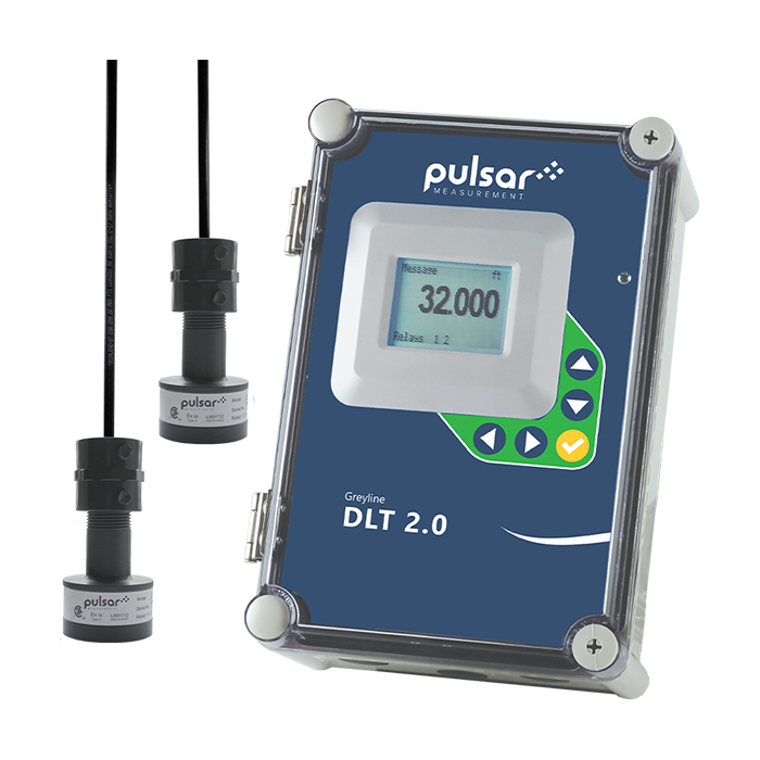
The DLT 2.0 Differential Level Transmitter is a simple solution for differential level measurement including applications found in wastewater treatment plants, pump stations, and combined sewer systems. The Differential Level Transmitter includes two differential level sensors. Position each sensor at your desired location, above a channel, up and downstream from a bar screen for example, and the DLT 2.0 can display and transmit differential level measurement. The downstream sensor could even be positioned above a flume or weir to measure and totalize open channel flow.
To make the most out of your DLT 2.0, install one sensor on each side of a mechanical bar screen to continuously monitor level. Using the built-in relays or 4-20mA outputs to automatically activate the bar screen rake at pre-set levels. Three 4-20mA outputs are configured to transmit upstream level, downstream level (or flow), and differential level. The built-in relays of the Differential Level Transmitter can be calibrated for level control, differential level control, or open channel flow.
Other applications for the DLT 2.0 include two-tank inventory, where you can monitor levels within two tanks with just one instrument, aiding stock control and process efficiency. The Differential Level Transmitter will alternate a display of level in both tanks, plus it will transmit 4-20mA outputs.
- Measures Level, Differential Level, and Open Channel Flow
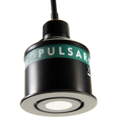
- Two, Non-Contacting Ultrasonic Sensors
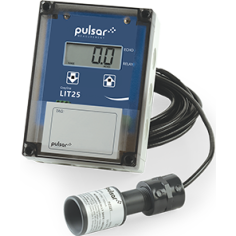
- Large White Backlit LCD Display
- Three Isolated 4-20mA Outputs
- Built-in 5-Key Calibration
- 2 Programmable Control Relays
- Optional 2 Million Point Data Logger
- Optional Intrinsically Safe Sensors
| General Specifications | |
|---|---|
| Spec name: | Description: |
| Electronics Enclosure | NEMA4X (IP 66) polycarbonate with clear, shatterproof cover |
| Accuracy | ±0.25% of range or 2 mm (0.08 in), whichever is greater. Repeatability and Linearity: ±0.1% |
| Display | White, backlit matrix - displays upstream, downstream, and differential level, open channel flow and totalizer, relay states, operating mode, and calibration menu |
| Programming | Built-in 5-key calibrator with English, French, or Spanish language selection |
| Power Input | 100-240 V AC 50/60 Hz (see Options), 3 W maximum with standard features |
| Outputs | 3 x Isolated 4-20mA, upstream and downstream level (or open channel flow), and differential level, 1000 ohm maximum |
| Control Relays | 2 total, rated 5 A SPDT; programmable for level control, differential control, or flow proportional pulse |
| Operating Temperature (Electronics) | -20 °C to 60 °C (-5 °F to 140 °F ) |
| Approximate shipping weight | 6.8 kg (15 lbs) |
| PZ15 Sensor Specifications (Includes 2 PZ15 Sensors) | |
|---|---|
| Spec name: | Description: |
| Maximum Range | 4.57 m (15 ft) with standard PZ15 sensor |
| Deadband (Blanking) | Programmable, Minimum 203.2 mm (8 in) |
| Beam angle | 8° |
| Operating Frequency | 92 KHz |
| Exposed Materials | PVC |
| Operating Temperature | -40 °C to 65 °C (-40 °F to 150 °F) |
| Temperature Compensation | Temperature probe inside the level sensor for high accuracy in changing temperatures |
| Sensor Cable | RG62AU coaxial, 7.6 m (25 ft) standard length (see Options) |
| Options | |
|---|---|
| Options: | Description: |
| Sensors | 10 m (32 ft) measurement range / Intrinsically safe models |
| Sensor Cable | 15 m (50 ft) or 30 m (100 ft) RG62AU coaxial continuous from the sensor - or splice up to a total of 150 m (500 ft) with optional JB watertight NEMA4 steel with connection terminal strip |
| Power Input | 9-32 V DC |
| Extra Control Relays | 4 additional (6 total) rated 5 A SPDT |
| Data Logger | 2 million point logger with USB output and Windows software - 3 channel logging (A & B sensors plus Differential or Open Channel flow |
| Enclosure Heater | Thermostatically controlled - recommended for temperatures below 0 °C (32 °F) |
| Intrinsic Safety Barriers | For sensor mounting in Class I, II, III, Div. I, II, Groups C, D, D, F, G hazardous locations |
| Sensor Mounting Stand | Adjustable, includes galvanized steel pipe, flanges, fittings, and hardware |
| Sunscreens | Sensor sunscreen and enclosure sunscreen for outdoor installations |
| Product Brochure | Download |
| Datasheet | Download |
| Order Form | Download |
| Installation & Instruction Manual | Download |
| Pulsar Logger v3.0.0 Software (Formerly Greyline Logger) | Download |
| Software Brochure | Download |
| North America Electrical Safety Certificate | Download |
| North America Haz Loc Certificate | Download |
| Datasheet | Explosion Proof Enclosure | Download |
| Datasheet | Greyline Enclosure Panel Mount | Download |
| Datasheet | PZS | Download |
| Datasheet | SBMS Submergence Shield | Download |
| Datasheet | SCR Enclosure Sun Screen | Download |
| Datasheet | SP5 Surge Protection | Download |
| Pulsar Measurement Product Warranty | Download |
- NEMA4X (IP 66)
- Intrinsic safety barrier for sensor mounting in Class I, II, III, Div. I, II, Groups C, D, D, F, G hazardous locations - Optional
- CE
- CSA/UL EN61010-1
- FM/CSA Class 1, Div 1
- FM/CSA Class 1, Div 2
Request a Quote
Quick form, fast quote — within 1 business day.
Product Works with

Product Configurator
The Pulsar Measurement product configurator allows you to select the applications specific to you and discover the most appropriate solutions for your requirements.