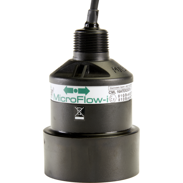
The MicroFlow-i is a non-contacting velocity measurement solution. Its extremely low power makes it an ideal velocity measurement solution for remote sewer network access points that are difficult to reach and often have no main power supply. Its lightweight, compact design makes installation simple, especially within confined spaces, and requires no interruption to normal operational flow.
MicroFlow-i Options
The MicroFlow-i range has been specified and designed to meet the demanding requirements of today’s process flow measurement applications. The unit is positioned above and at 45 degrees to the flow and measures flow velocity.
The standard RS485 version is Ex mb certified for use in Zones 1 and 2, and the 2-wire loop-powered version with HART protocol is intrinsically safe (Ex ia) for Zone 0.
MicroFlow-i Communication
The 2-wire version can be used in a digital HART mode or as a 4-20mA loop-powered device. The MicroFlow-i can be set up using a HART modem with either proprietary HART software such as PACTware, or MicroFlow HART PC software.
Event Duration Measurement for Combined Sewer Overflows
Management of pollution under flood conditions is a significant challenge, and with ever more demanding monitoring regimes, operators have implemented thousands of CSO monitoring installations and thousands more are planned, with data logging and level measurement to record spill events.
Level is only one part of the equation, as we can now add velocity sensors above a channel to measure the flow velocity.
Measuring velocity using a non-contacting technique is a very complex challenge analytically and has only really become realistic with the faster processors now available. Here at Pulsar Measurement, we use a technique called Refracted Spread Spectrum Analysis. In the MicroFlow-i a pulse is fired at the liquid surface, producing a mass of reflections from the full width of the channel, a single transducer handling channels up to 1.5 m (4.0 ft) width and multiple transducers working together for wider applications, applying the RSSA algorithms to analyze and integrate the received signals, then ‘slicing’ them for real-time analysis and velocity calculation.
To find out more about how to use the MicroFlow-i in the field, visit the Downloads tab and read our case studies.
- Non-contacting
- Extremely low power consumption
- Lightweight, compact, and rugged design
- Minimal installation costs with no interruption to service
- Maintenance-free
- Cost-effective
- Optional mounting bracket available
| General Specifications | |
|---|---|
| Spec name: | Description: |
| Sensor Body Dimensions: | 90 mm x 140 mm (3.54 in x 5.51 in) |
| Weight: | 1 kg (2.2 lbs) |
| Sensor Body Material: | Valox 357 |
| Maximum Separation: | Up to 1,000 m (3,280 ft) |
| Max. and Min Temperature (Electronics): | -20 °C to +60 °C (-4 °F to +140 °F) |
| Velocity Range: | 0.3 m/s to 6 m/s (0.98 ft/s to 19.7 ft/s) |
| Optimum Installation: | Install and an angle of 45° in line with the flow. More information is available in the manual. |
| Outputs: | HART and 4-20mA loop-powered |
| Options | |
|---|---|
| Options: | Description: |
| Mounting Bracket | Convenient bracket for optimal mounting of sensor |
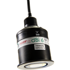
| dBi Loop-Powered Sensors | For a complete area-velocity measurement |
| Point Connector | Fitted to cable (with fuse) |
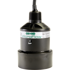
| MicroFlow | Optional Modbus or Pulsar Controller version |
| Product Brochure | Download |
| Datasheet | Download |
| Installation & Instruction Manual | Download |
| Technical Drawing (UNCONTROLLED COPIES) | Download |
| Microflow-i PC Software V1.2.0 | Download |
| Version 1.0.11 (HART) Firmware | Download |
| Version 0.0.8 Firmware ONLY | Download |
| Ex ia Certificate | Download |
| FM Certificate of Conformity (US) | Download |
| FM Certificate of Conformity (CAN) | Download |
| Ex ia Certificate | Download |
| MicroFlow & MicroFlow-i FM Manual | Download |
| Pulsar Measurement Product Warranty | Download |
- IP68
- CE approval
- ATEX Ex II 1 G D
- ATEX Ex ia IIC T4 Ga
- ATEX Ex ia IIIC T135 °C Da (Directive 2014/34/EU)
Request a Quote
Quick form, fast quote — within 1 business day.
Product Works with


Product Configurator
The Pulsar Measurement product configurator allows you to select the applications specific to you and discover the most appropriate solutions for your requirements.